Shell and tube heat exchanger is a commonly used equipment in industry. The article below will describe this type of exchanger.
Shell and Tube heat exchanger uses
Shell and Tube Heat Exchangers are the most commonly used in the chemical processing industries today. It possesses large surface areas for heat transfer and is capable of operating at high temperatures and pressures.
Shell and tube heat exchangers are frequently selected for applications such as:
- Process liquid or gas cooling
- Process or refrigerant vapour or steam condensing
- Process liquid, steam or refrigerant evaporation
- Process heat removal and preheating of feed water
- Thermal energy conservation efforts, heat recovery
- Compressor, turbine and engine cooling, oil and jacket water
- Hydraulic and lube oil cooling
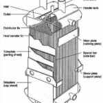
Shell and tube heat exchangers consists of an outer shell surrounding a nest or bundle of tubes, that are parallel to the longitudinal axis of the shell.
Shell and Tube heat exchanger types
The principle types of shell and tube heat exchanger are:
Fixed tube plate, U tube and Floating head, this in turn doesn’t limit it to only three types but more types are
present depending on demands however the three types mentioned are the most commonly used and designed in industry. The types of shell and tube are conventionally classified according to nomenclature of the Tabular Exchanger Manufacturer’s Association (TEMA), TEMA sets the standards for shell and tubeheat exchangers, these standards are followed and used worldwide by engineers, see TEMA classifications below,

From the image above the most common types can be classified as follow
BEM – Fixed tube plate
This type of exchanger is probably used more often than any other type. The construction is simple and economical and tube bores can be cleaned mechanically or chemically. However, the outside surface of the tubes is inaccessible except to chemically cleaning. If large temperature differences exist between the shell and tube materials, it may be necessary to incorporate an expansion bellows in the shell to eliminate excessive stresses caused by expansion

BEU – U tube
The tube bundle consists of a stationary tube sheet, U tubes (or hairpin tubes), baffles or support plates, and appropriate tie rods and spacers. The tube bundle can be removed from the heat-exchanger shell. A tube-side header (stationary head) and a shell with integral shell cover, which is welded to the shell, are provided. Each tube is free to expand or contract without any limitation being placed upon it by the other tubes. The U-tube bundle has the advantage of providing minimum clearance between the outer tube limit and the inside of the shell for any of the removable-tube-bundle constructions. Clearances are of the same magnitude as for fixed-tube-sheet heat exchangers. The number of tube holes in a given shell is less than that for a fixed tube-sheet exchanger because of limitations on bending tubes of a very short radius. The U-tube type of exchanger is able to absorb the stresses due to thermal expansion. A disadvantage of the U-tube design is that it cannot have pure counter flow (except with F-type shells) and this gives a consequential penalty on effective temperature difference (ΔT). This type of exchanger is similarly priced to the fixedtube type when operating at low pressure, but shows a significant saving at high operating pressures.

BES – Floating head
This type of heat exchanger is suitable for the rigorous duties associated with high temperatures and pressures. The tube bundle consists of straight tubes secured into tube plates at each end. The tube sheet at the tube-side fluid inlet end is of larger diameter than the shell and is sealed in a similar manner to that used in the fixed tube-sheet design. The tube bundle is easily removed for cleaning or maintenance and the tubes can be cleaned both inside and outside. The floating head design is more expensive (approximately 25%) than the tube-sheet design.

Other types may be required for certain process or maintenance reasons. Removable covers (A or L type heads) may be desired for access to tubes without disturbing pipe-work. Integral tube sheets (C or N type) would be considered for higher pressure or high temperatures where they are cheaper than removable covers, and where gasketed joints need to be minimised. The T type of floating head is similar to the S type but has a more robust tube sheet to floating cover joint at the expense of greater bypass area around the bundles (and, thus larger shells) and,
therefore, is more expensive. However, with the T type, the bundle may be removed without dismantling the floating head assembly, unlike the S type, thus reducing maintenance time. The W and P type floating heads utilise packed glands and are therefore limited on application by pressure and temperature. They are suitable for applications where leakage of the gasket joint is to atmosphere. The P type is considerably more expensive than the W type. The NEN configuration is sometimes found to be an economic option.
The various configurations may be listed in order of increasing cost (left to right) as follows:
Front end: B, N, C, A
Rear end: U, M, N, L, W*, S, T, P* (* Limited application)
Baffle Types
All designs has a part called Baffle plate or Baffles they are generally a plate the tubes pass through for support that provides a blocked path for the shell side flow, which forces the flows across the tubes and improves the heat transfer performance. This is shaped in various ways, but is basically segmental.
Below are the main baffle types and orientation, also shown with arrows the flow pattern around each baffle:
(a) Segmental baffles

(b) Segmental & strip

(c) Disc and doughnut

(d) Orifice

The single and double segmental baffles are most frequently used. They divert the flow most effectively across the tubes. The baffle spacing, however must be chosen very carefully. Optimum baffle spacing is somewhere between 0.4 and 0.6 of the shell diameter and a baffle cut of 25% to 35% usually recommended. The triple and no-tubes-in-window segmental baffles are used for low pressure drop applications, which are approximately 0.5 and 0.3 of the segmental value. No-tubes-in-window construction eliminates the tubes that are otherwise supported only by every second baffle, thus minimising tube vibration.
Disc-and-ring (doughnut) baffles are composed of alternating outer rings and inner discs, which direct the flow radially across the tube field. The potential bundle-to shell bypass stream is thus eliminated; there are some indications that the baffle type is very effective in pressure drop to heat transfer conversion. At present, these baffles are rarely used in the United States but are popular in Europe. Another type of plate baffle is the orifice baffle, in which shell-side fluid flows through the clearance between tube outside diameter and baffle-hole diameter. Rod or grid baffles are formed by a grid of rod or strip supports. The flow is essentially longitudinal, resulting in very low pressure drops. Because of the close baffle spacing, the tube vibration danger is virtually eliminated. This construction can be used effectively for vertical condensers and reboilers
To see the difference between tube and shell passes please check “What is the difference between shell passes and tube passes” article
Useful books
1. Hewitt, G.F., Shires, G.L., Bott, T.R., Process Heat Transfer, 1994 CRC Press, Inc.
2. Hewitt, G.F., Hemisphere handbook of heat exchanger design, Hemisphere Pub. Corp., c1990
3. Bell, K- J. (1973), Thermal design of heat transfer equipment, in Chemical Engineers Handbook, 5th ed., Perry, R.H. and Chilton, C. F., Eds.
4. Standard of Tubular Exchanger Manufacturers’ Association, Tubular Exchanger Manufacturers’ Association (TEMA) (1988), Association, 7th ed., TEMA, New York.
5. Kern, D. Q. (1950), Process Heat Transfer, McGraw-Hill, New York.
6. Kakac, S., Hongtan, L., Heat Exchangers Selection, Rating and Thermal Design, 2nd Edition, CRC Press LLC
8. Cavaseno, V., Process Heat Exchange, McGraw-Hill, New York
Useful Software
Shell & Tube Heat Exchanger Design (S&THex) – By Khaled Aljundi – Webbusterz Engineering Software – webbusterz.com
Shell & Tube Condenser Design (CnD) – By Khaled Aljundi – Webbusterz Engineering Software – webbusterz.com


