Heat exchangers comparison
The table below compares different heat exchangers mainly common types
| Heat exchanger type | Maximum pressure | Temperature range | Fluid limitation | Normal size ranges for individual unit | Special features |
| Air-cooled | High on process side (500 bar). | High temperature possible on process side (up to 600°C). | Subject only to material of construction. | 5 to 350 m2 (bare tube) (per bundle multiple bundles often used). | Heat rejection system. Requires fans. Tubes normally finned. |
| Shell and tube | 300 bar (shell). 1400 bar (tube). | 25 to 600°C (lower and higher with special materials). | Subject only to materials of construction. | 10 to 1000 m2 (per shell multiple shells can be used). | Very adaptable and can be used for nearly all applications. |
| Brazed-plate | 16 bar | Up to 200°C. | Suitable for liquids compatible with braze material. | 1 to 10 m2 . | Modular construction.not easily cleaned. |
| Double-pipe (plain and finned tubes) | 300 bar (shell) (higher pressures possible with special design). 1400 bar (tube). | 100 to 600°C (higher with special materials). | Subject only to materials of construction. | 0.25 to 200 m2 per unit multiple units are often used. | High thermal efficiency, standard modular construction. |
| Electric tubular heat exchangers | 300 bar | Up to 700°C. | Subject only to materials of construction. | 3 to 650 kW. Multiple units used for larger capacity. | Special control systems can be used to minimise impact on electrical supply. |
| Glass-tube | c. 1 bar | Up to 250°C. | Low pressure, suitable for corrosive fluids. | Stainless steel often used in structure. | |
| Graphite | 20 bar | 50°C to 165°C. | Corrosion resistant unless fluid attacks resin. | 0.2 to 60 m2. | High corrosion resistance. |
| Spiral | 18 bar | Up to 400°C | Subject only to materials of construction. Often used for fouling duties. | Up to 200 m2. | High heat transfer efficiency. Cylindrical geometry useful as integral part of distillation tower. |
| Heat-pipe | Near atmospheric. | <200°C (higher with special heat pipe fluids). | Low pressure gases. | 100 to 1000 m2. | Near counter-flow operation possible. Extended surface possible on both sides. |
| Plastic tube | 1 bar | Up to 100°C. | Low pressure,suitable for corrosive fluids. | Stainless steel often used in structure. | |
| Plate-and-frame | 25 bar with some models up to 40 bar. | 25 to 175°C (40 to 200°C possible for very special types) | Normally unsuitable for gases. Limitation is on gaskets. | 1 to 2500 m2 | Modular construction. Normally the most economical if applicable. |
| Plate-fin | 100 bar (aluminium). 200 bar (stainless steel), | 273 to + 150°C (aluminium) (up to 600°C in stainless steel), | Low fouling. | <9 m volume | Very small AT possible. Incorporation of multiple streams. Very large surface area per unit volume. |
| Printed-circuit | 1000 bar | 800°C (with stainless steel material limited). | Low fouling. | to 1000 m2 | Very large surface area per unit volume. Stainless steel or higher alloys normal construction material. |
| Rotary regenerators | Near atmospheric, | Up to 980°C. | Low pressured gases. | Inter-stream leakage must be tolerated | |
| Scraped- surface | 10 bar. | Up to 300°C. | Liquids subject only to materials of construction. | 5 to 10 m height, 0.5 m dia. | Suitable for viscous and crystallisation systems |
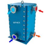
| Welded-plate | 60 bar (higher in shells). | In excess of 65 0°C. | Subject only to materials of construction. Not suitable for fouling duties. | > 1000 m2 | Differential pressure should be less than 30 bar. Differential expansion should be borne in mind. |
Thanks for viewing heat exchangers comparison table


