Introduction
The heat exchanger safety factor calculation is a fundamental part of heat exchanger design that ensures reliable performance under real operating conditions. While theoretical calculations assume ideal conditions, actual systems experience fouling, property variations, and operational fluctuations.
A proper heat exchanger safety factor calculation provides a margin that guarantees the exchanger will continue to meet process requirements even as conditions change over time.
Why Safety Factor is Needed
In real systems, uncertainties arise from:
- Fouling buildup
- Flow rate variations
- Temperature fluctuations
- Property estimation errors
The heat exchanger safety factor calculation accounts for these uncertainties.
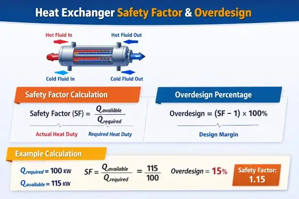
Definition of Safety Factor
Where:
- = actual heat transfer capability
- = process duty
Heat Duty Fundamentals
The heat transfer rate is given by:
This equation is central to the heat exchanger safety factor calculation.
Step-by-Step Safety Factor Calculation
Step 1: Calculate Required Duty
Step 2: Calculate Available Duty
Step 3: Calculate Safety Factor
Example Calculation
Given:
- Required duty = 100 kW
- Available duty = 115 kW
This indicates 15% excess capacity.
Overdesign Calculation
Relationship with Fouling
Fouling reduces heat transfer over time. Therefore:
- Clean condition → higher U
- Fouled condition → lower U
The heat exchanger safety factor calculation ensures performance even under fouled conditions.
Typical Design Values
| Service Type | Safety Factor |
|---|---|
| Clean fluids | 1.05 – 1.10 |
| Moderate fouling | 1.10 – 1.20 |
| Heavy fouling | 1.20 – 1.30 |
Engineering Interpretation
- SF = 1 → exact design (not recommended)
- SF > 1 → safe design
- SF too high → unnecessary cost
Practical Design Considerations
When performing a heat exchanger safety factor calculation, engineers must consider:
- Maintenance intervals
- Fouling rates
- Process criticality
- Cost vs reliability
Integration with Design Software
In modern tools, safety factor is often used to:
- Automatically size area
- Adjust margins
- Evaluate performance
Common Mistakes
- Confusing safety factor with fouling factor
- Using arbitrary margins
- Ignoring real operating data
- Overdesigning excessively
Advanced Considerations
Dynamic Safety Factor
Some systems adjust safety factor based on:
- Operating history
- Real-time performance
Economic Optimization
Optimal safety factor minimizes:
- Capital cost
- Operating cost
References
- Kern, D.Q. – Process Heat Transfer
- Coulson & Richardson – Chemical Engineering
- Incropera & DeWitt – Heat Transfer
- TEMA Standards
Conclusion
The heat exchanger safety factor calculation is essential for ensuring long-term reliability and performance. By carefully selecting an appropriate safety margin, engineers can balance efficiency, cost, and operational stability.
Try This Calculation Using Software!
Shell and tube heat exchanger software